Formula SAE
I was the mechanical lead of the team for the 2016-2017 season on my school's Formula vehicle racing team, Olin Electric Motorsports. Currently, I am the aerodynamics and composites team lead, heading an aerodynamics package from scratch and mentoring new members. We compete against other collegiate teams every year at the Lincoln airfield in the electric division of the competition and are pursuing our third year as a team.
Over the time that I've been with the team, I've gained heavy experience in mechanical design, DFM, DFA , managing a team to a strict project schedule, and collaborating with other engineers.
The video on the right depicts me testing the vehicle to collect IMU data, and is the product of my team's sweat and passion.
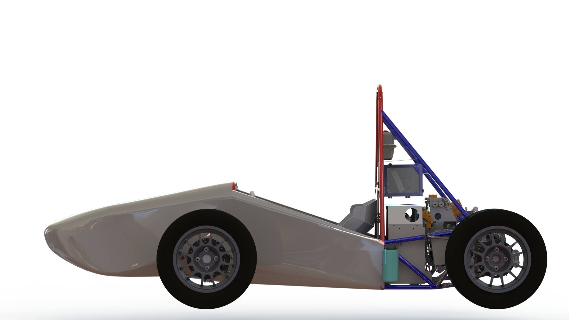
Formula Vehicle CAD
As the mechanical lead for the project 2017, I was in charge of ensuring all the systems came together. The team's work resulted in this SolidWorks assembly, comprising of 1463 separate parts.
We regularly held internal design reviews to make sure team members were on track to meet our deadlines, and also held design reviews with professionals at General Motors to expand our team's knowledge.
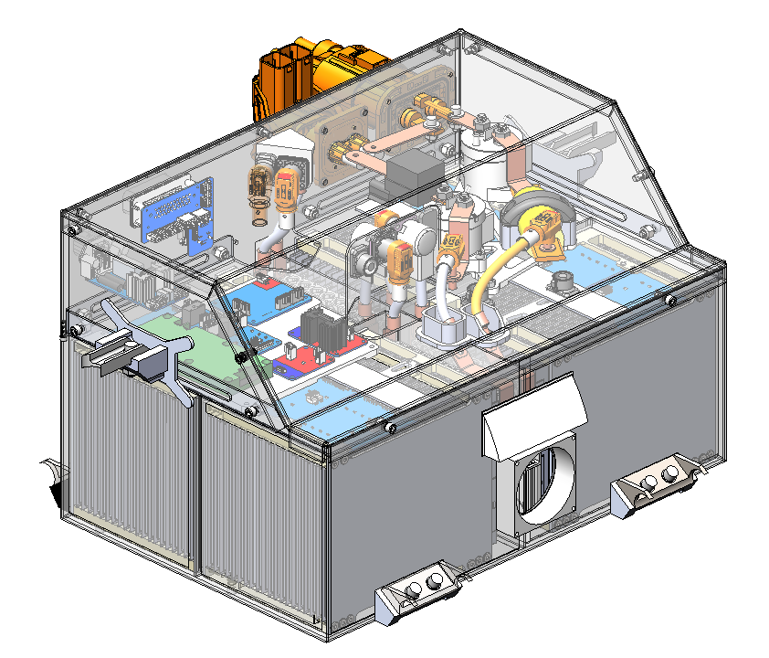
Accumulator
Last year, I spearheaded many of the accumulator design requirements such as the mounting, service section, and high-level decisions.
In addition to considering important factors for Design for Manufacturing and Assembly, I had to ensure that HV components were Poka-Yoke and could not be inserted incorrectly. In addition, the packaging consideratons for the accumulator were extremely vital since it weighs over 50kg. This meant developing a hydraulic mounting method and designing around 00 AWG HV wire bend radii.
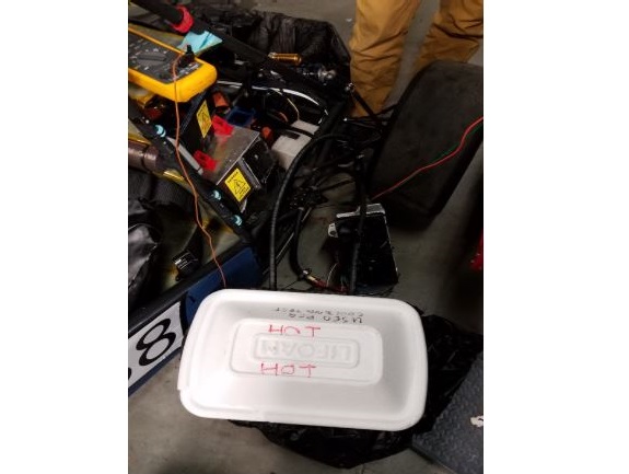
Radiator Validation Testing
One of our areas of risk was the radiator and cooling system we had designed a year prior.
I helped to put together a cooling test that would validate the calculations performed by the previous team on the cooling rate of the set-up. In order to account for the ambient temperature, we ran a control test that did not use the radiator fans. Temperatures were reported using a thermocouple and a thermometer for confirmation.
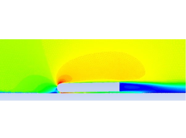
Undertray Initial CFD
As some of the preliminary work done for this year, I have performed CFD analysis on an Undertray mock-up to justify design decisions.
This model was produced primarily to characterize the effects of vehicle pitch and ride height on Undertray performance. The boundary conditions include a moving floor and Pressure Far-Field to simulate a moving vehicle. It is not perfectly accurate since it is only a simple 2D analysis and is not physically validated. However, comparing the different parameters against itself is enough justification for our decision-making.
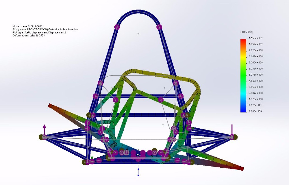
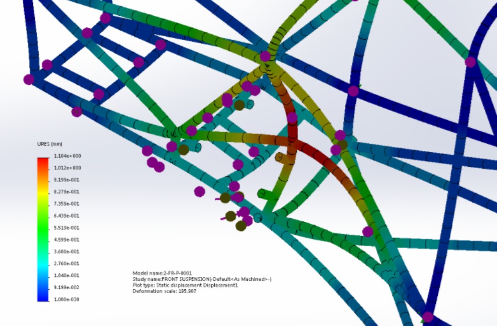
Frame Torsional Analysis
In addition to managing the mechanical team, I led the design of the chassis, and performed some basic analysis to meet our requirements.
My research suggested that the vehicle's minimum torsional stiffness should be 1000 lb-ft/deg, and my calculations resulting from SolidWorks Simulation gave a value of 1069.3 lb-ft/deg given a 2400N load, the approximate weight of our vehicle.
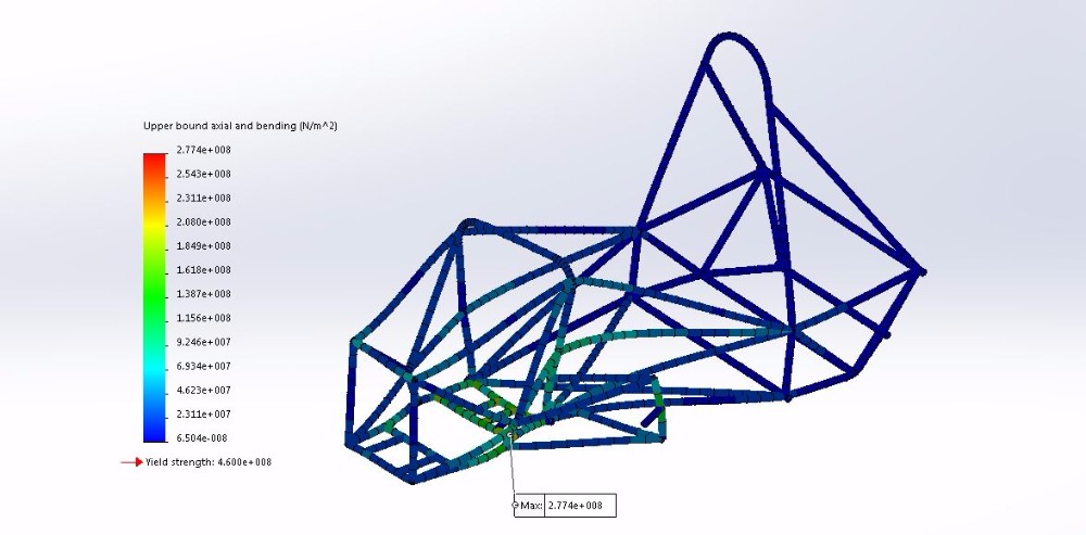
A-Arm Stress Analysis
In addition to torsional stiffness analysis, I analyzed the stress from braking loads on the frame.
The attachment points of the A-arms were not on nodes of the chassis. To alleviate this concern, I verified the frame would not yield under the worst case, and saw a factor of safety of almost 2.
A-Arm Stress Analysis
To further validate my previous analysis, I performed calculations in MATLAB that generated loads on each of the four nodes to which the A-Arms are attached.
The resulting stresses and deflection made it clear that our chassis was strong enough to handle the loads.
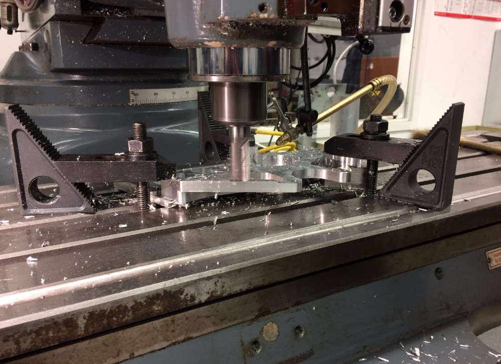
Upright Manufacturing
In addition to analysis, I manufactured many components on the race car. One of those components was the front upright which is pictured on the left in the final phase of being milled.
The contours of the upright were made with CNC Milling. The bearing fits on the part were made with a boring head, and required indication to bore the other side of the component.
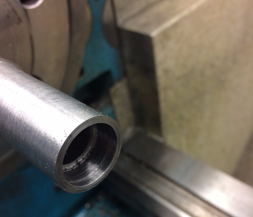
Spherical Bearing Housing
I also machined smaller components such as this steel housing for a spherical bearing. This required the use of a boring tool on the lathe to achieve the 0.003" tolerance.
The specific alloy of steel for the stock was originally unidentified since it was old and unlabeled. Because this needed to be welded to our A-Arms, I took a small sample and tested it on an XRF machine to check that it was 4130 Chromoly Steel.
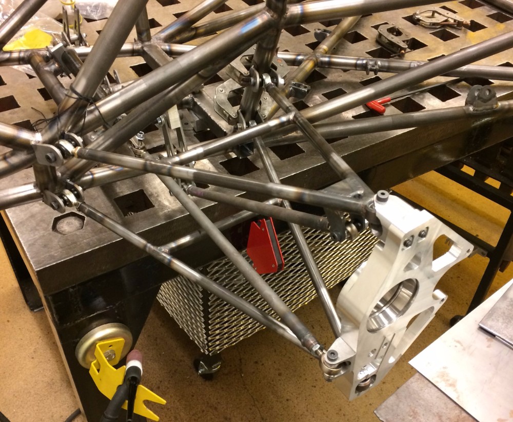
Suspension Welding
I welded most of the components onto last year's car including the the suspension. After plasma-cutting and post-manufacturing the tabs, I jigged up the entire suspension to ensure that our geometry would operate how it was simulated.
The image on the left depicts all the string, magnets, and clamps used to hold the tabs in place while I tacked them in their correct orientation.
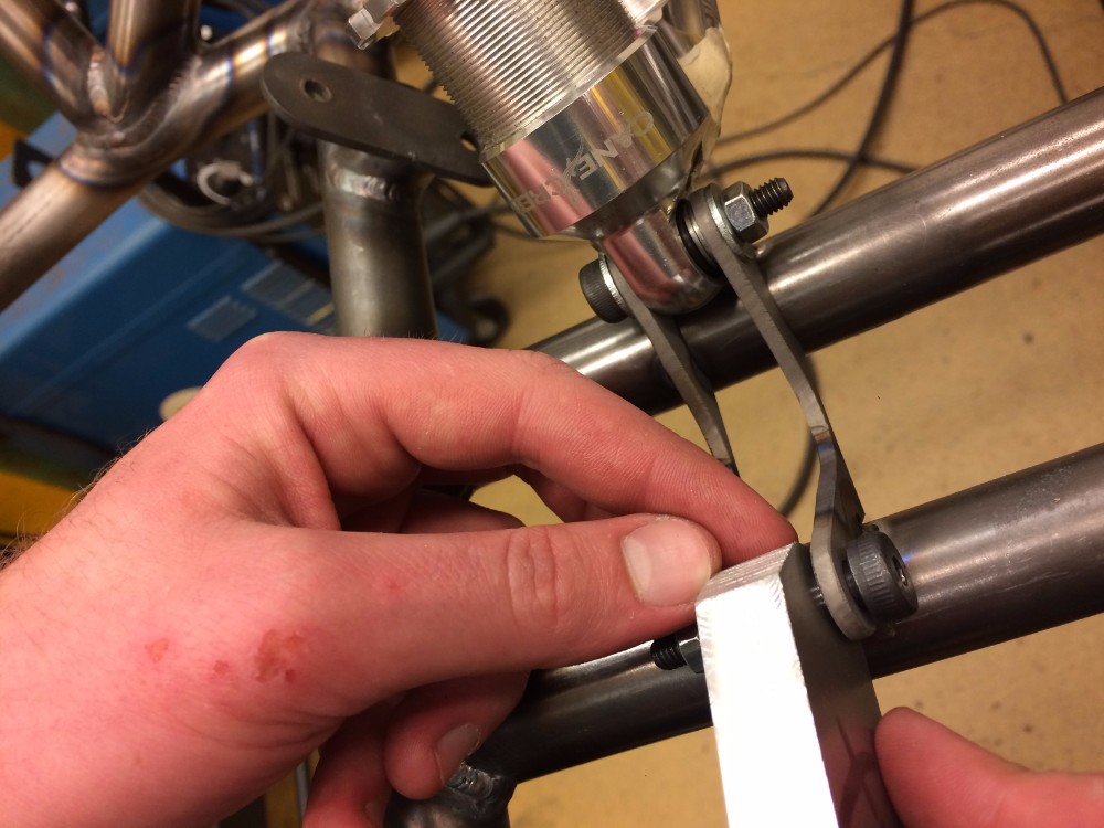
Welding Fixtures
To achieve the precise hole locations required for suspension and other components of the car, I used many custom fixtures to replace heat sensitive components while I welded.
As seen in the photo on the left, the jig has holes spaced apart at the shock's length while the car is in its neutral position.
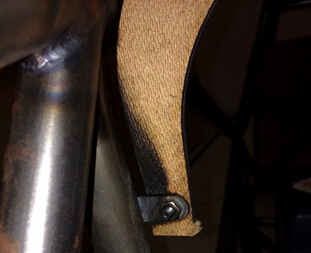
Welding Fixtures
This MDF fixture is another example of measures I took to make sure my components were all in the right place.
In this case, I replaced the nylon dashboard with a lasercut template that allowed me to weld this locating tab in the correct location.
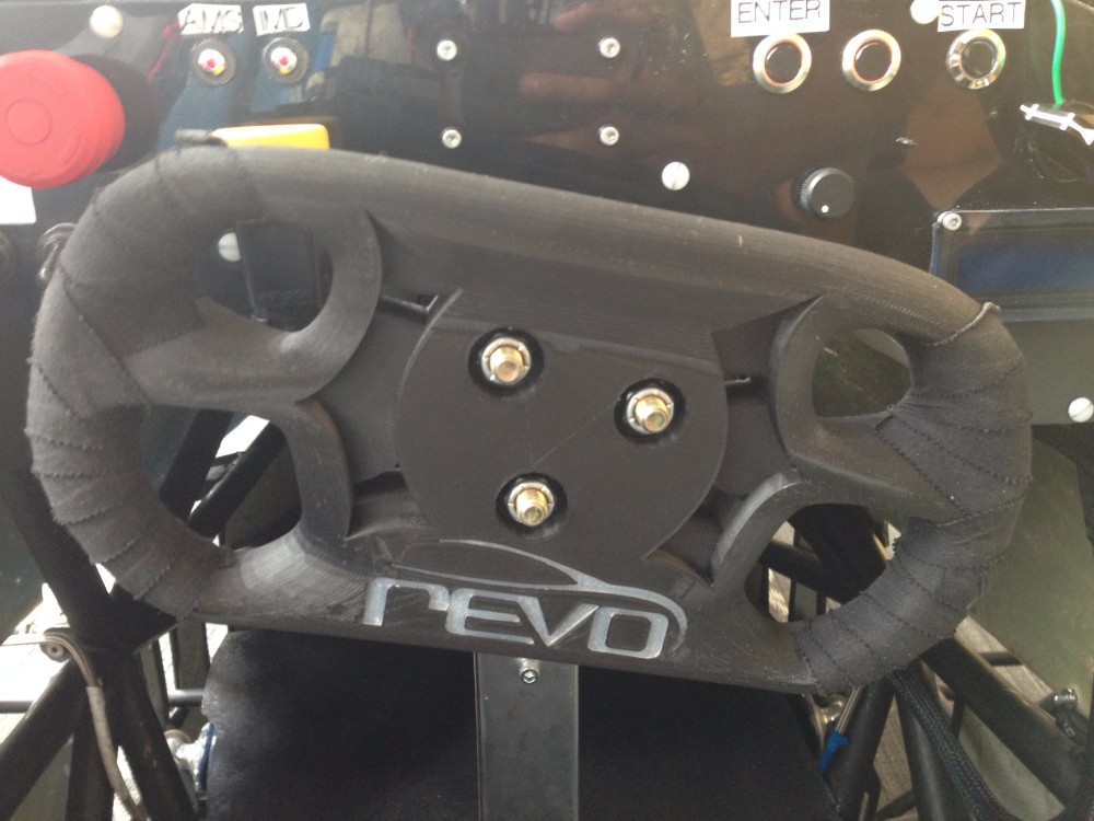
Steering Wheel
As a first year on the team, one of my projects was to design steering wheel for our drivers. This steering wheel was designed in Fusion 360 and printed out of carbon-fiber embedded nylon for weight.
I developed this steering wheel by looking for inspiration from current Formula cars. To achieve the best driver ergonomics, I printed multiple iterations of the steering wheel to receive feedback from the drivers.
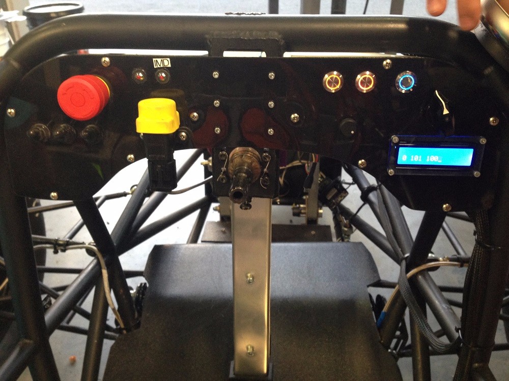
Dashboard
Another component I designed as a first year was the dashboard. It has a nylon front and 3D-printed compartments for housing electronics.
Because it has many embedded electronic components, I worked with the electrical team to spec out rules compliant components that would reach my ingress protection requirements.
Dashbaord Waterproofing
In order to create an IP65 compliant dashboard, I used O-rings in both the front and the back to keep water out.
The dashboard was designed such that maintenance could be performed on the PCB very easily. The thermal-press inserts keep the back lid on until the insides of the dashboard need to be accessed.
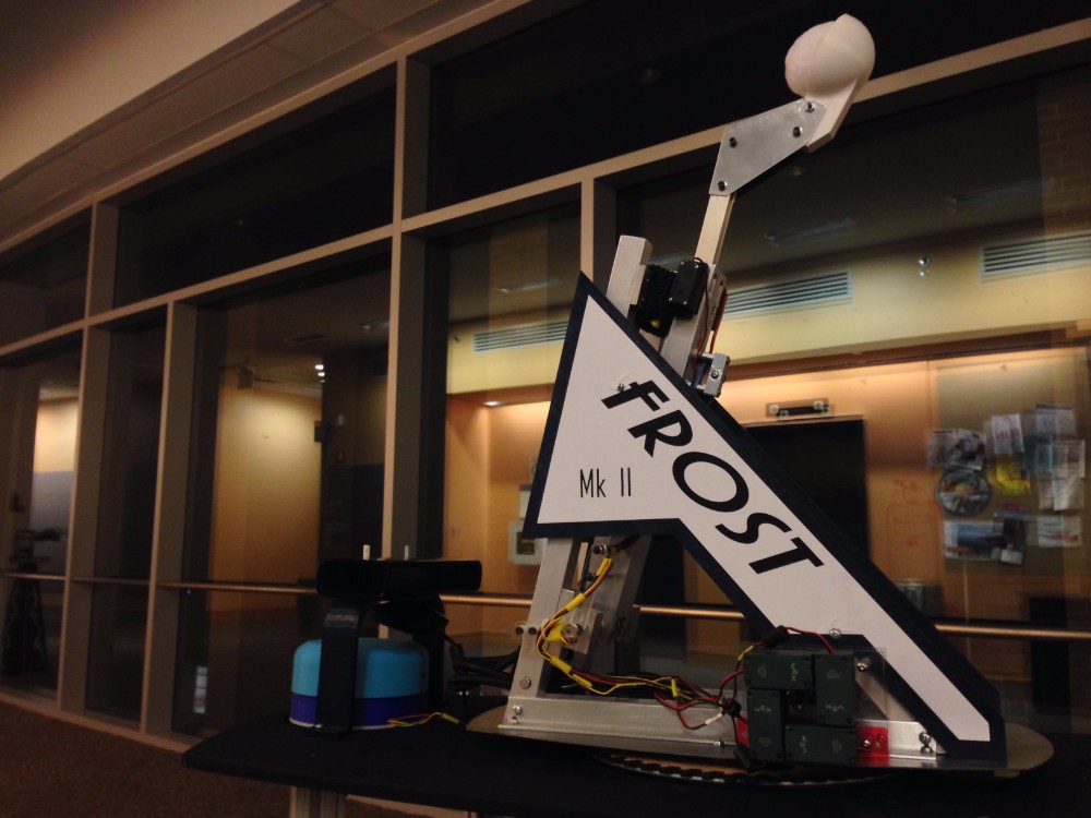
FROST Autonomous Snowball Launcher
This project was the result of a team effort in a semester-long mechatronics course. The catapult tracks humans with a kinect and has a LIDAR to detect the distance from the target before launching a snowball in their direction.
This project was featured on the BostINN ONewsletter and a link can be found on the left.
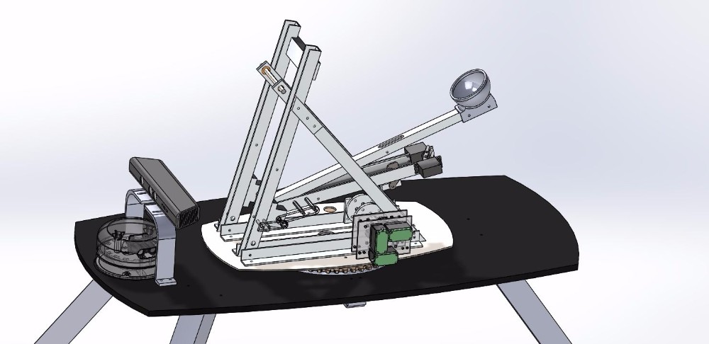
Project CAD
The full CAD of this project is depicted on the left.
The assembly is held on a stand, and contains a LIDAR and Xbox Kinect for vision tracking. The rotating catapult is placed in the center of this assembly.
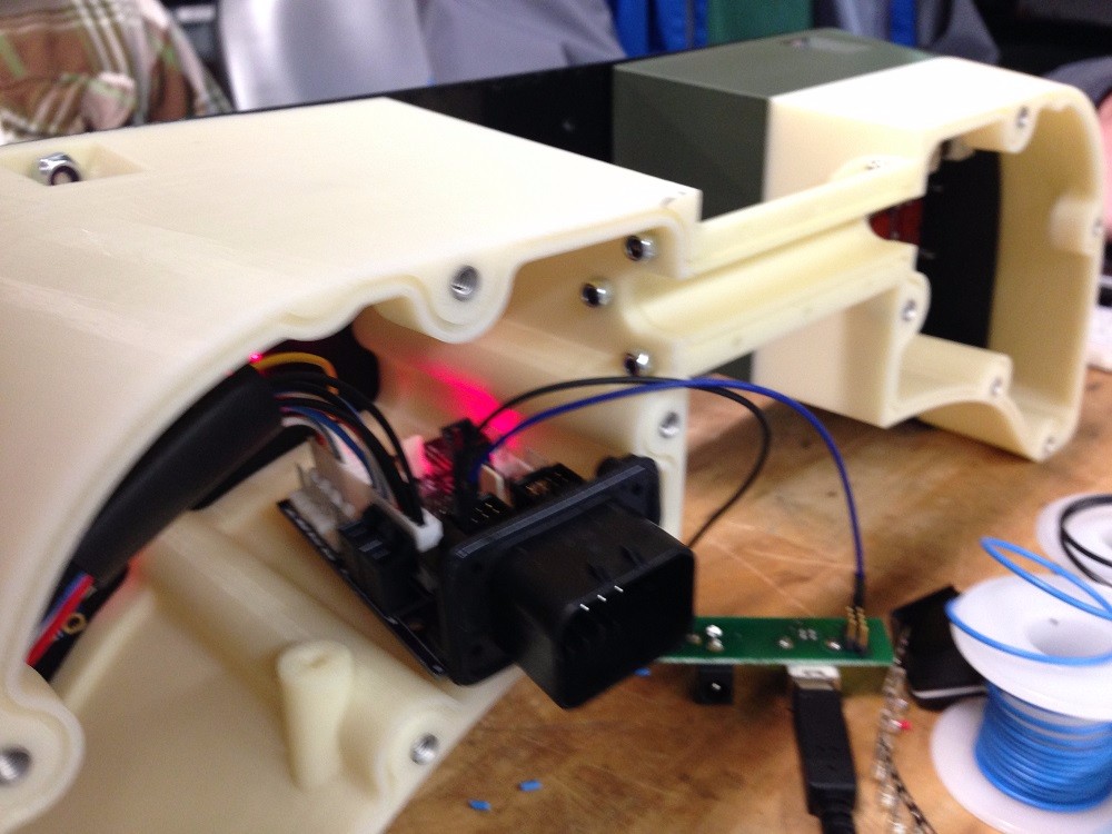
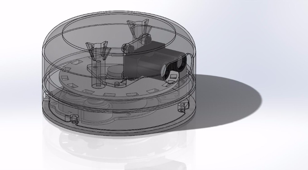
DIY LIDAR
To track the distance of targets from the catapult, my partner and I created a LIDAR using a LIDAR-Lite V3 off Sparkfun. A typical 360-view LIDAR was magnitudes above our budget so we settled for a DIY version.
With the $200 LIDAR, we used a slip ring to transfer data and power while keeping track of the LIDAR position with a custom encoder.
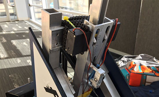
Catapult Mechanism
The catapult is constantly in tension through the use of surgical tubing. However, a retracting arm comes up to bring the main arm down for reloading and shooting.
The two arms connect with each other via a hook actuated by two servos, which disengages to release the snowball upon unsuspecting victims.
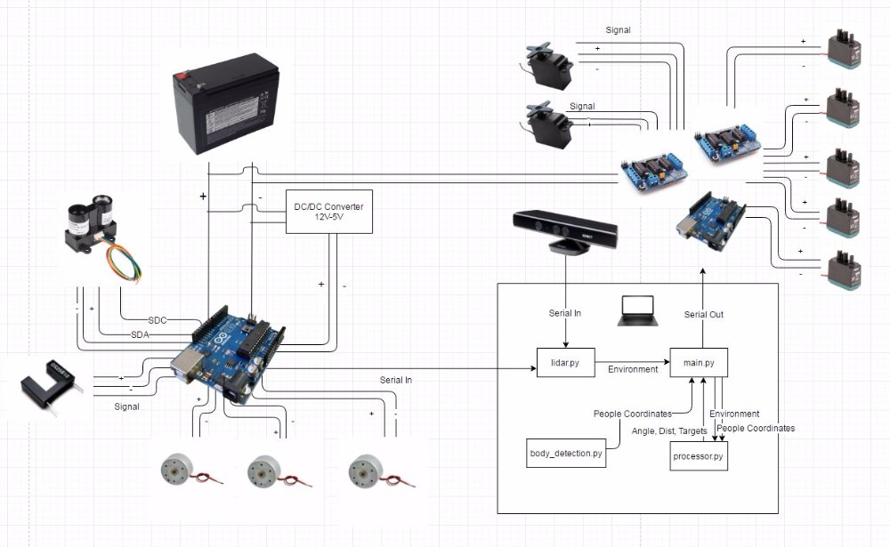
Schematic
The overall system schematic is shown on the left.
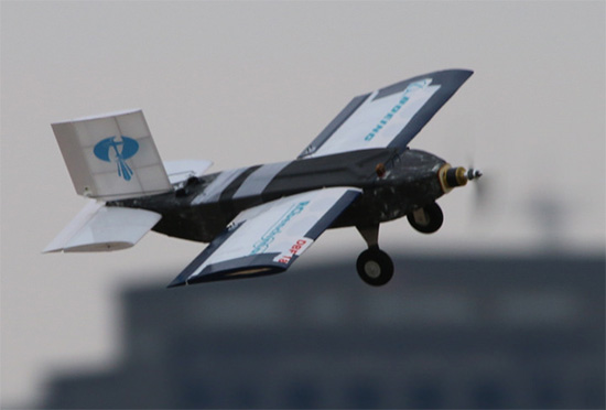
Design Build Fly
In 2017 I was the structures lead for our school's new Design Build Fly Team. I performed design and testing work as well as extensive manufacturing on the plane we designed for the compeition.
Ultimately, we placed 11th out of 100 teams in our first year and developed a strong foundation for future year.
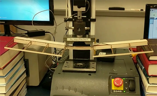
Four Point Bend Test
In order to validate analysis done on the wings, I performed Instron four point bend tests on various wing manufacturing methods. The strongest wing withstood 15lbs of force, leaving us with a FOS of over 2.
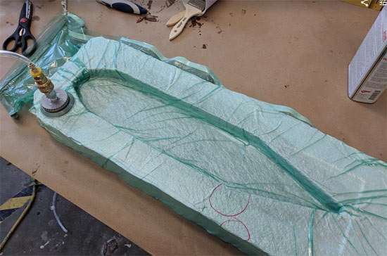
Fuselage Vacuum Wet-Layup
In our second iteration of our fuselage, we created a carbon fiber plane for stiffness and decreased weight.
The molds are manufactured out of XPS foam due to its cheapness and ease of machinability. However, this method is more time-consuming than higher-quality materials. We then performed a two-piece wet layup that we fit together to form our fuselage.
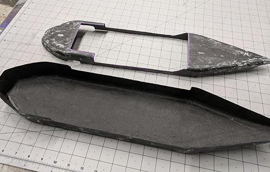
Carbon Fiber Body
The finished product of our lay up is shown on the image to the left. We were very pleased with the weight of the parts as there were only two layers of cloth and our batting absorbed a majority of the epoxy.
The components were post-manufactured to fit tightly within each other and provide mounting surfaces for other components of the plane.
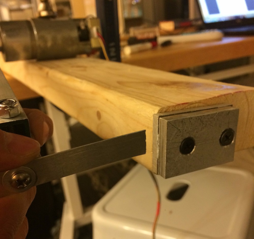
Bending Fatigue Study
I created a fixture with a partner to test different metal dogbones. We ran them over different bending stresses to characterize the changes in fatigue life.
The fixture included a motor running at a speed of 1hz, and pushed/pulled a linkage to load the dogbone cyclically.
Video
The video to the left shows one of the higher stress cycles as it breaks.
Using data from the dogbone tests, I used MATLAB to plot and compare the results with results found online. The longest cycle we ran lasted 12 hours with a relatively small stress.
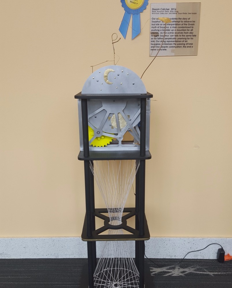
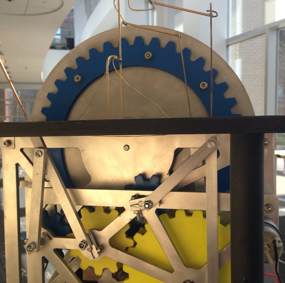
Kinetic Sculpture
This sculpture was built as part of a project for my first year mechanical prototyping class. It depicts a boy, Sisyphus' Son, chasing after a kite through eternity.
My involvement includes ideation, mechanical design of linkages and cams, CAD and assembly packaging, and overall fabrication. The sculpture was designed to last through many cycles of use, and is still being used as a demo sculpture for new classes.
Linkages
The linkages attached to the legs of the boy move in sync in order to simulate a walking motion. The speed was calculated such that the walking speed of the boy matches the tangential velocity of the flywheel.
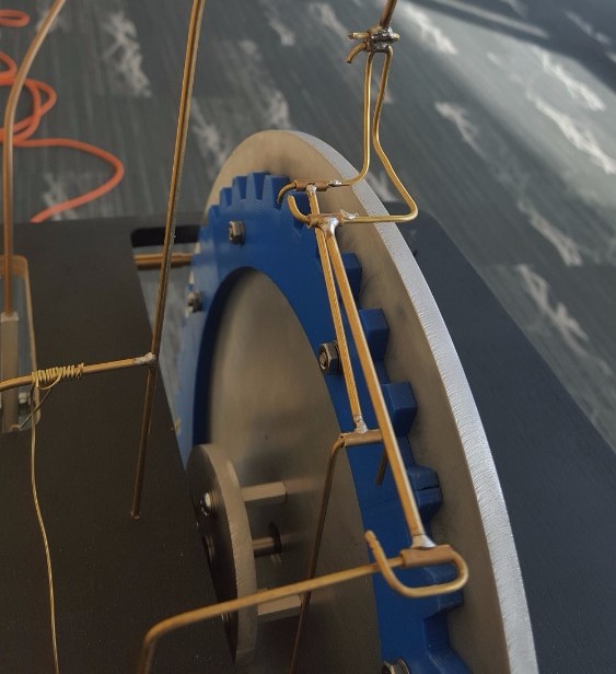
Cams
A 3:4 ratio of gears is attached to the bell-cranks that move the linkages of the kite. The effect of the gear ratio is a sense of randomness in the kite's motion as if it were billowing a wind.
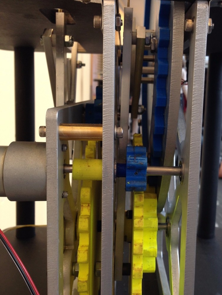
Gearbox
This side view of the gearbox shows the inner workings of the sculpture. The numerous gears have been sanded and lubricated with lithium grease to reduce the resistance against the single motor being used.
Video
The video on the left takes you through a tour of the entire sculpture.
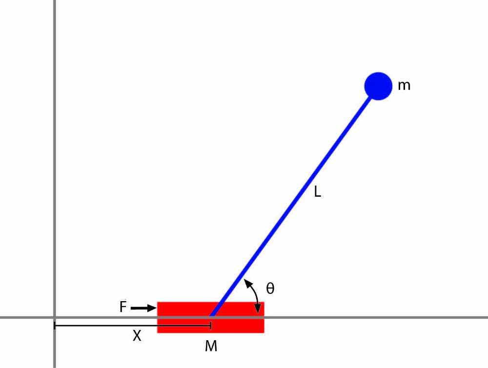
Inverted Pendulum
This MATLAB simulation was developed for a course in my first year at Olin.
The simulation takes in the initial velocity of the cart and initial angle of the pendulum, and self-balances the pendulum.
Lagrangians and PID
This MATLAB simulation was created through Lagrangian equations my partner and I derived from the diagram on the left.
However, we wanted to maintain the position of the pendulum so we also implemented PID into our equations.
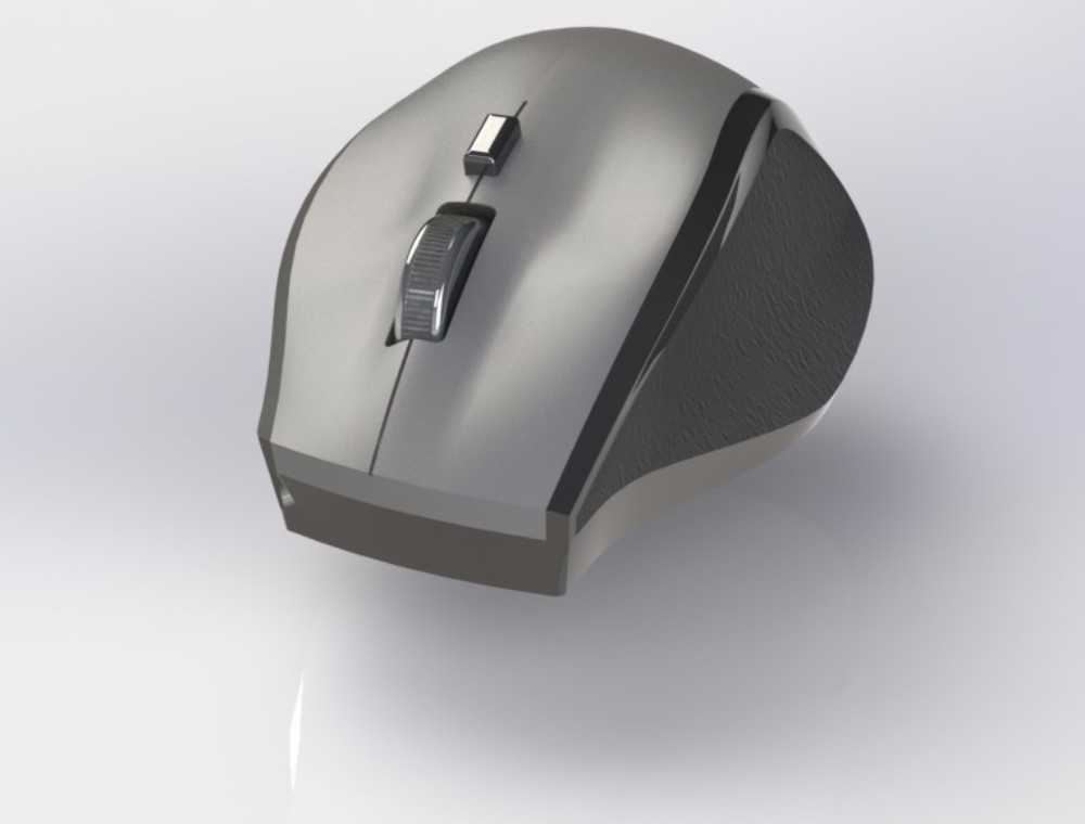
Logitech Mouse
This is a render of a Logitech M705 mouse I modeled in SolidWorks.
The project enabled me to better understand 3D surfacing, including boundaries and lofts, in 3D modeling.
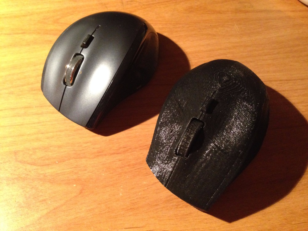
Real Life Model
I 3D printed the SolidWorks model in order to compare my work to the actual M705 mouse. The 3D printed mouse in general has the same shape as the actual mouse. However, its dimensions are a little different in some areas due to measurement inaccuracies..
In order to achieve a spinning scrollwheel, I created custom supports that I could easily break after the part was printed.
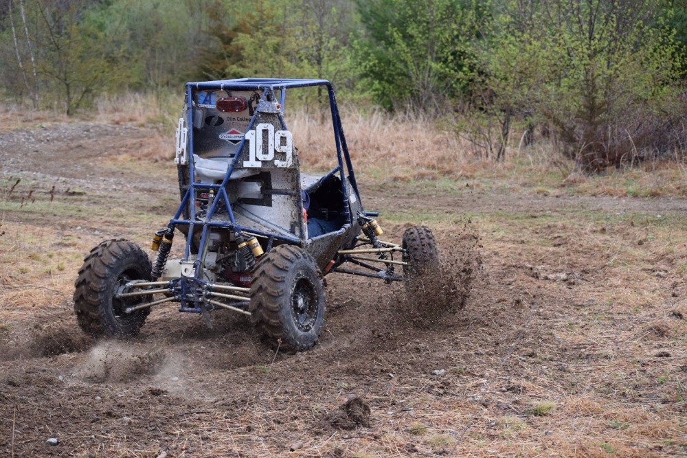
BAJA
The Baja SAE competition is geared towards designing an offroad vehicle with ability to withstand unpredictable terrain while maintaining speed.
On the team, my main role was in design of the transmission. I worked with a team of two other students to design a test rig to tune our CVT and modified the previous year's gearbox.
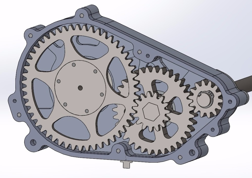
Gearbox
This is a cut section view of the gearbox I designed for the 2016 vehicle.
The modified design is 2/3 the weight of the original while maintaining a factor of safety of at least 1.5 for all components inside the gearbox.
CVT Test Rig
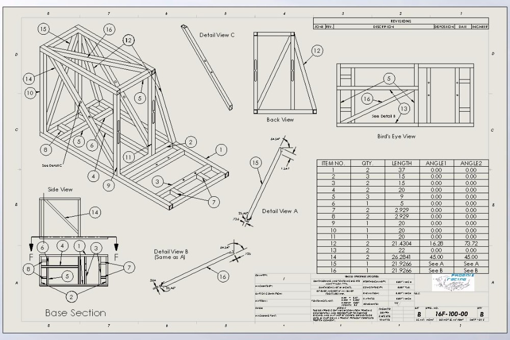
The drawing on the left depicts the CVT test rig I designed with a partner.
The rig simulates the load the engine undergoes with a large flywheel and enables us to fine tune the CVT for performance. To ensure safety, the flywheel is enclosed by 0.65" thick square tubes and the feet are vibration-damping.
Play Project
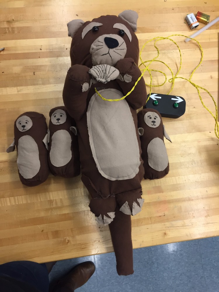
I was a member of a 5 person team that designed an educational play experience for fourth graders with a theme of otters.
This image is of the remote control otter that our team developed for the fourth grader's experiences. In order to engage the fourth graders, we kept the controls simple and made the otters appealing in appearance.
Play Environment
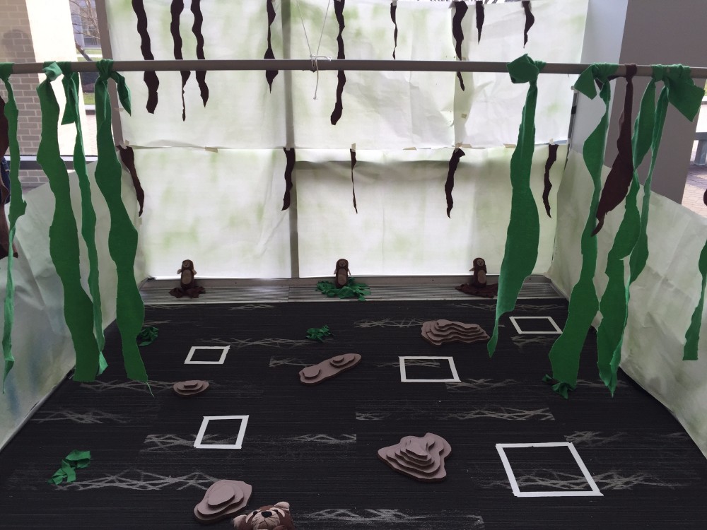
One of our goals was to immerse the fourth graders in the experience by creating a sea-like environment in our given space.
The goal of the game was to retrieve each of the baby otters at the end before 'nightfall' in order to demonstrate the communal nature of sea otters.
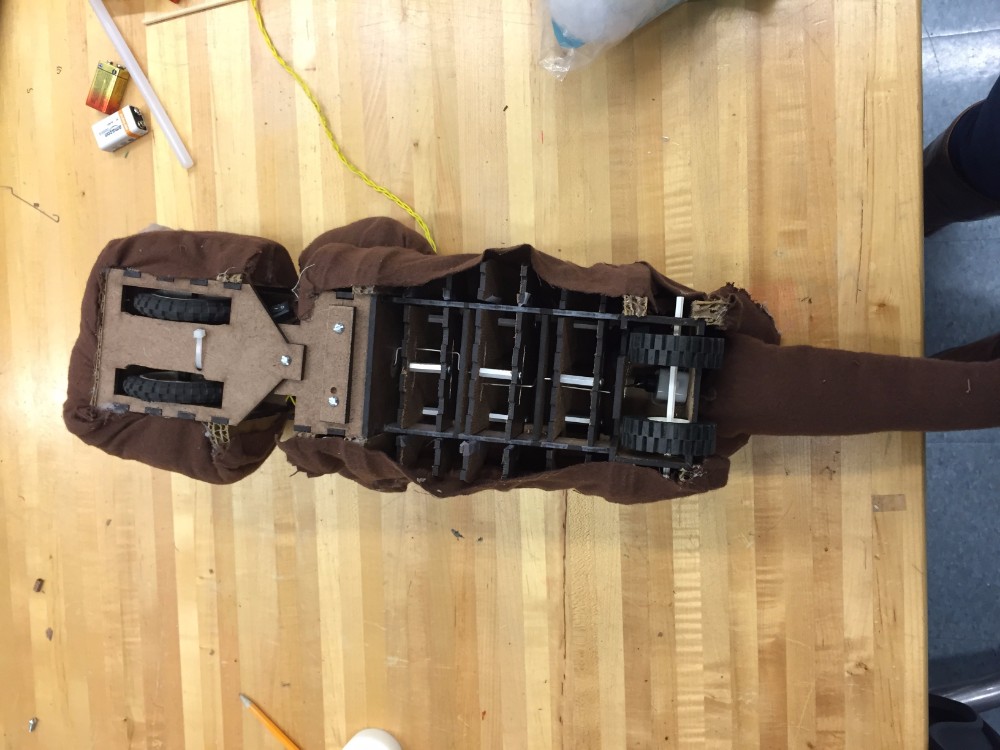
Mechanical Components
The image on the left shows the otter's inner workings.
An electrically powered crankshaft generates the sinusoidal motion of a sea otter swimming and two other motors control its direction and forward motion.
Hopper
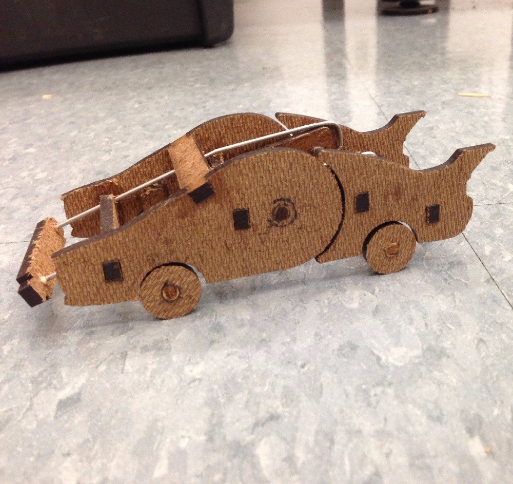
This car was created for a design engineering class where my formulated goal was to produce excitement and inspire young children to pursue engineering. It is pushed and rolls along a surface until collision, upon which it will jump over the obstacle.
Collision
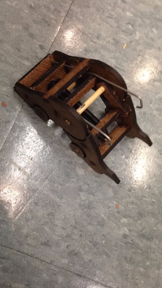
This is the position the 'hopper' takes after being triggered. The two end of the car collapse inward to drive the body upward through elastic bands along the bottom of the car.
The latch used for the locking mechanism is disengaged after a collision.
Slo-Mo Video
The video on the left is a slo-mo of the hopper in action.
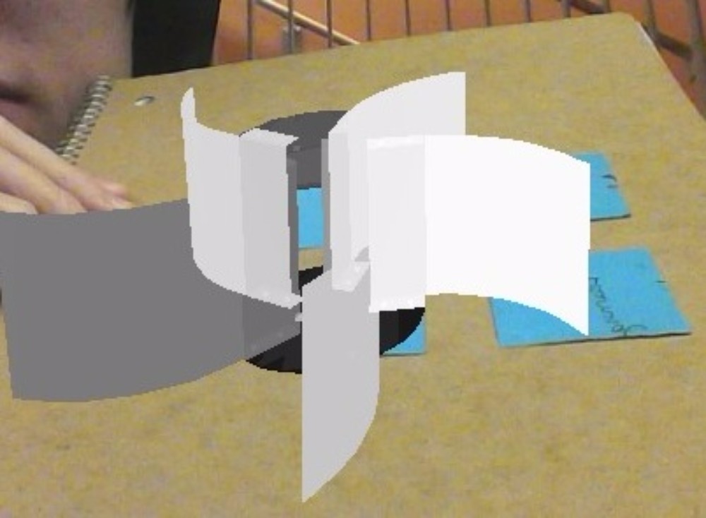
Augmented Reality
As a member of a four person team, I helped to create an augmented reality program to view STL files in python.
Using the four corners of the identifying surface, the program would project a rotating CAD file at any position. This was calculated using math involving quadrants to locate each corner and the identifying corner.
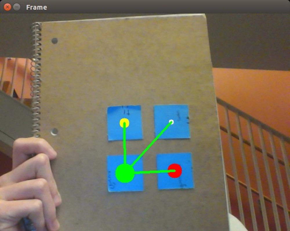
Initial Development
Using the identified surface, the program then can generate a 3D vector space calculation using vision tracking calibration and homography, the relation of two image surfaces that helps produce a planar projection.
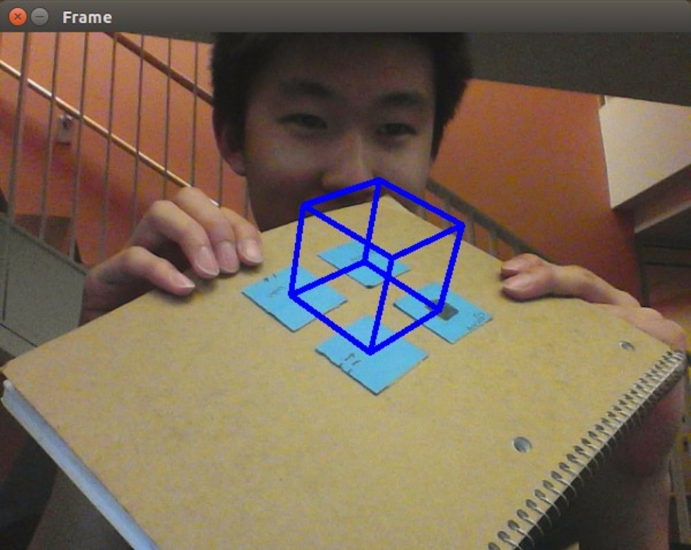
Working Prototype
This last image shows a CAD model being inserted into the program and being drawn in augmented reality on the chosen surface.
Exposition
Our team presented our project to the Olin Exposition at the end of the semester.
The video on the left shows a working demo using Google Cardboard.
Candy-Making
I worked on two candy-making pursuits over the past year, one with hard candy, and one with gummy candy.
The hard candy was a fun challenge of working with non-newtonian fluids quickly before they became too hard and tough to reshape. On the other hand, gummy candy was a much less stressful process that involved creating a mold for the sugar goo.
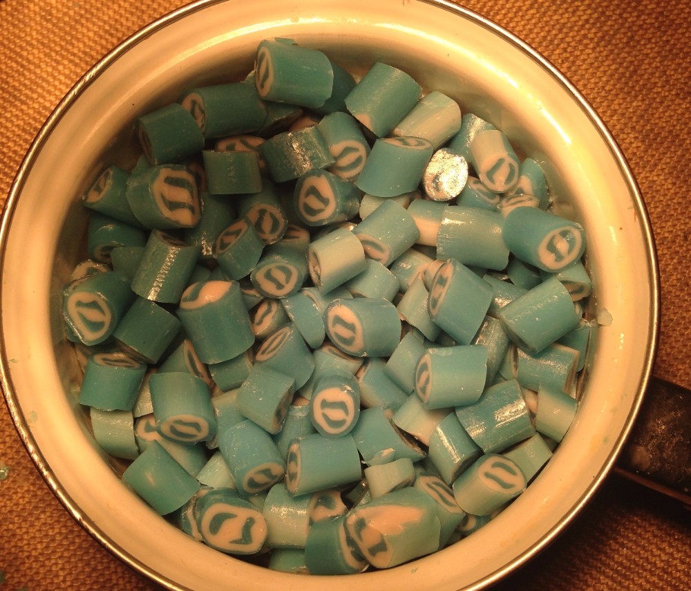
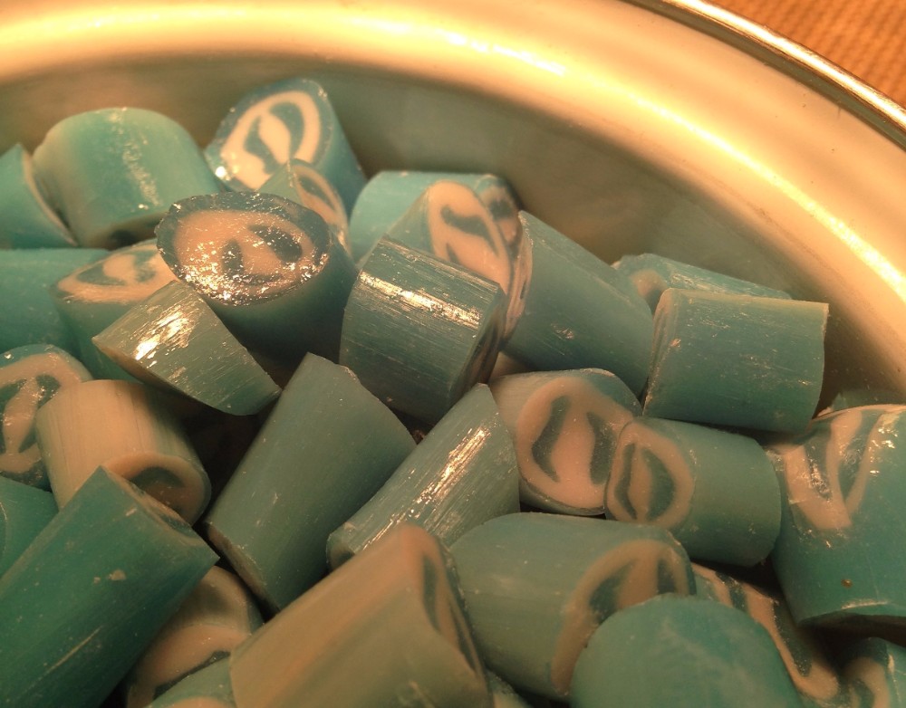
Shapes and Colors
After finishing a few batches of hard candy, my partner and I decided to try and make the Olin logo. The image on the left shows our resulting product, which we were pretty proud of. The taste was also quite something as well.
Gummy Bears
In our pursuit of making gummy candy, we initially started off with simple gummy bear molds so that we could make sure our gummy consistency was to our liking.
Custom Molds
We then moved onto custom molds such as the one shown on the left. Using Food-Grade Polypropylene filament, we printed out some fighter jets as our male mold.
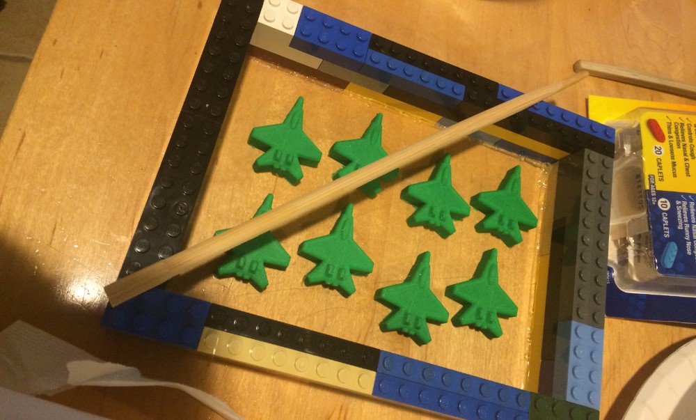
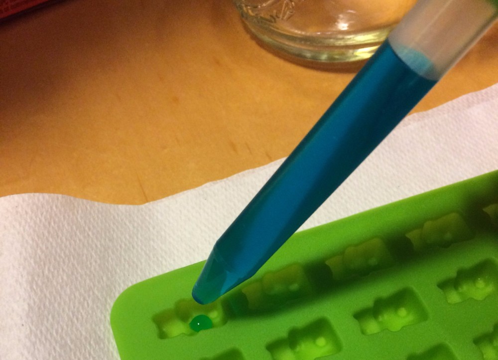
Silicone mixing
After securing the fighter jets to a smooth surface and enclosing it with LEGO bricks, we poured 2-part silicone over the top of the parts.
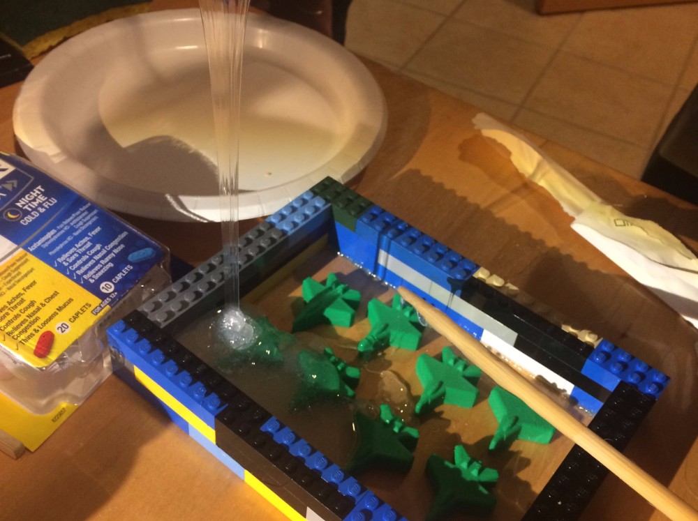
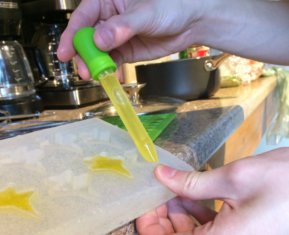
Finished mold
After waiting for the silicone to cure, we pulled the mold out and made some delicious gummy planes.